About
DHCP Relay Agentis the bridge between the client and the DHCP server. Through theDHCP Relay Agent, clients’ broadcasts can be received across different network segments, allowing the DHCP server to successfully assign IP addresses to clients.
Infrastructure
Configure multiple
vlangroups on a single router interface and assign IP addresses through the DHCP server across differentvlangroups.
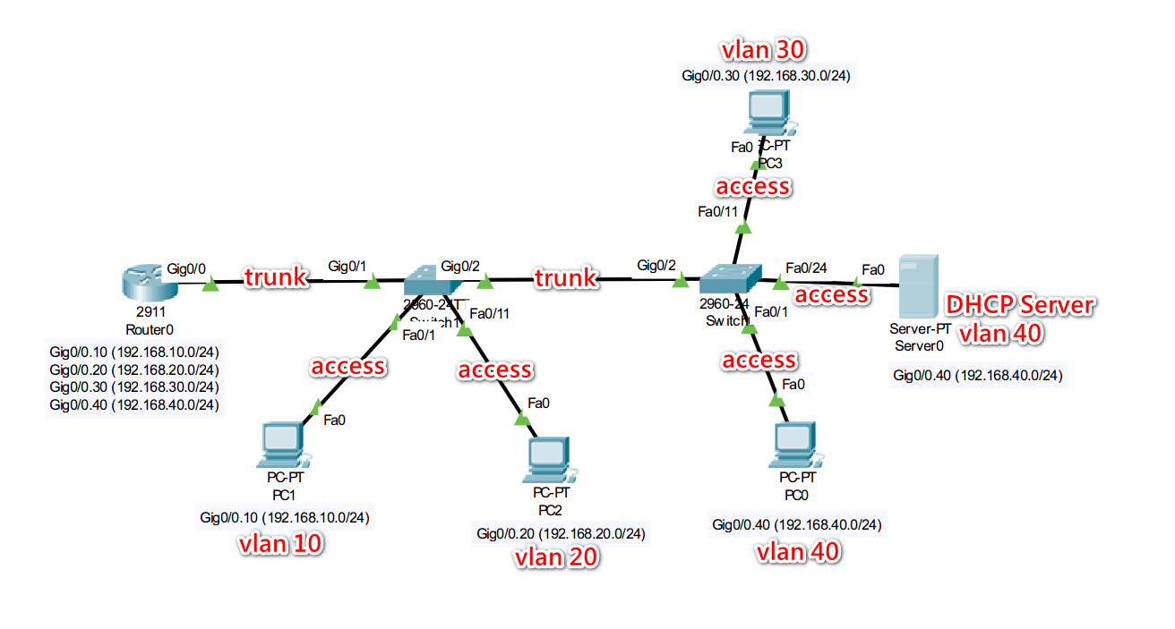
| vLan | IP(Subnet) |
|---|---|
| vlan10 | 192.168.10.0/24 |
| vlan20 | 192.168.20.0/24 |
| vlan30 | 192.168.30.0/24 |
| vlan40 | 192.168.40.0/24 |
PC1 in vlan10
PC2 in vlan20
PC3 in vlan30
PC0 in vlan40
DHCP Server (192.168.40.254) in vlan40, clients in all vlan (10, 20, 30, 40) can obtain IP addresses through the DHCP Server in vlan40.
DHCP Server Configuration
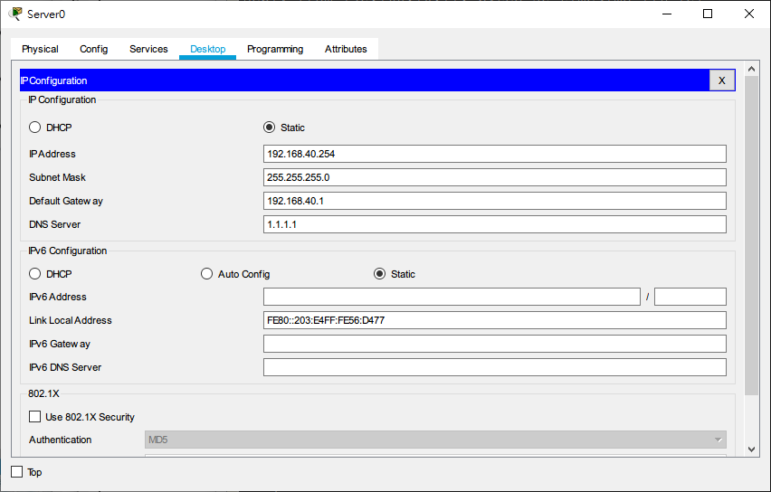
Set IP address to 192.168.40.254
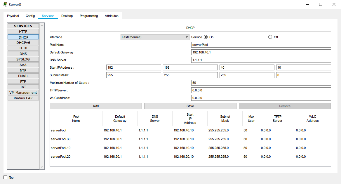
Create 4 DHCP address pools corresponding to Vlan 10, Vlan 20, Vlan 30, and Vlan 40.
Router Configuration (Cisco 2911)
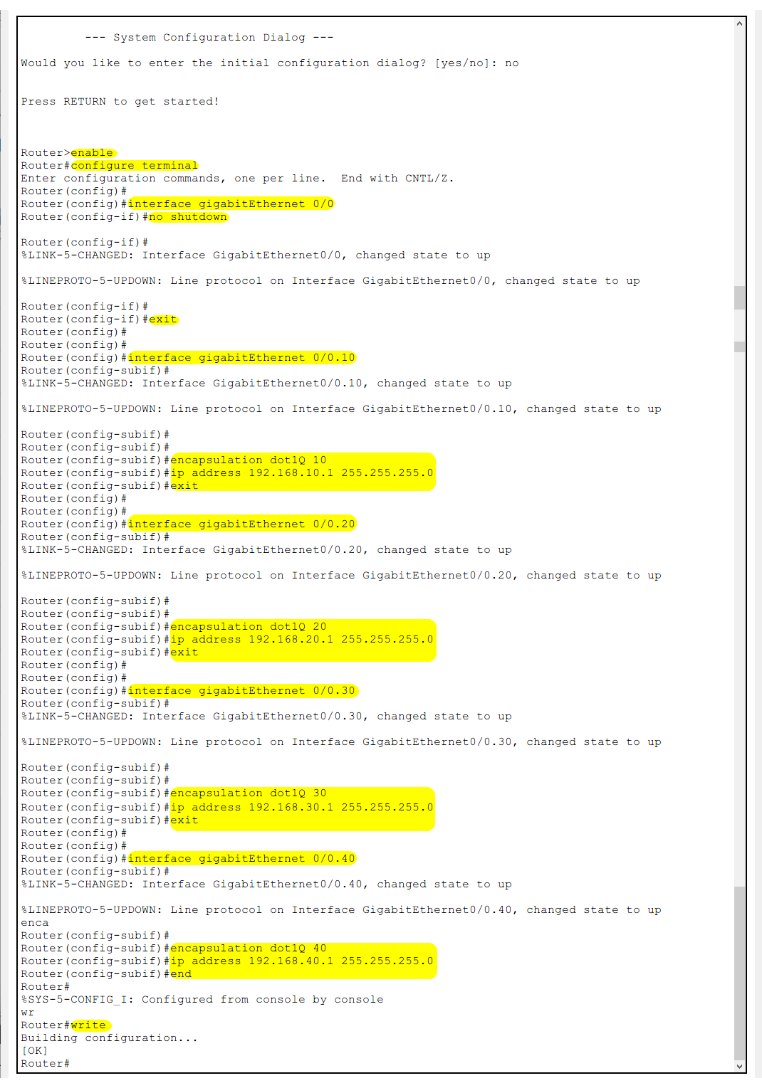
Router>enable
Router#configure terminal
Enter
Global Configuration Mode
Router(config)#interface gigabitEthernet 0/0
Router(config-if)#no shutdown
Router(config-if)#exit
Select physical interface 0/0 and enable it
Router(config)#interface gigabitEthernet 0/0.10
Router(config-subif)#encapsulation dot1Q 10
Router(config-subif)#ip address 192.168.10.1 255.255.255.0
Router(config-subif)#exit
Configure sub-interface on physical interface 0/0
Configure 802.1Q protocol and assign
vlan10Set interface IP address
ip address 192.168.10.1 255.255.255.0
Router(config)#interface gigabitEthernet 0/0.20
Router(config-subif)#encapsulation dot1Q 20
Router(config-subif)#ip address 192.168.20.1 255.255.255.0
Router(config-subif)#end
Configure sub-interface on physical interface 0/0
Configure 802.1Q protocol and assign
vlan20Set interface IP address
ip address 192.168.20.1 255.255.255.0
Router(config)#interface gigabitEthernet 0/0.30
Router(config-subif)#encapsulation dot1Q 20
Router(config-subif)#ip address 192.168.30.1 255.255.255.0
Router(config-subif)#end
Configure sub-interface on physical interface 0/0
Configure 802.1Q protocol and assign
vlan30Set interface IP address
ip address 192.168.30.1 255.255.255.0
Router(config)#interface gigabitEthernet 0/0.40
Router(config-subif)#encapsulation dot1Q 40
Router(config-subif)#ip address 192.168.40.1 255.255.255.0
Router(config-subif)#end
Configure sub-interface on physical interface 0/0
Configure 802.1Q protocol and assign
vlan40Set interface IP address
ip address 192.168.40.1 255.255.255.0
Configure IP Helper (DHCP Relay Agent)
Router(config)#interface gigabitEthernet 0/0.10
Router(config-subif)#ip helper-address 192.168.40.254
Router(config-subif)#exit
Add the IP Helper (DHCP Relay Agent) to sub-interface 0/0.10, pointing to the DHCP Server at 192.168.40.254
Router(config)#interface gigabitEthernet 0/0.20
Router(config-subif)#ip helper-address 192.168.40.254
Router(config-subif)#exit
Add the IP Helper (DHCP Relay Agent) to sub-interface 0/0.20, pointing to the DHCP Server at 192.168.40.254
Router(config)#interface gigabitEthernet 0/0.30
Router(config-subif)#ip helper-address 192.168.40.254
Router(config-subif)#exit
Add the IP Helper (DHCP Relay Agent) to sub-interface 0/0.30, pointing to the DHCP Server at 192.168.40.254
Router(config)#interface gigabitEthernet 0/0.40
Router(config-subif)#ip helper-address 192.168.40.254
Router(config-subif)#exit
Add the IP Helper (DHCP Relay Agent) to sub-interface 0/0.40, pointing to the DHCP Server at 192.168.40.254
Router(dhcp-config)#end
Router#write
Save
Switch Settings (Cisco 2960-24T)
Switch1
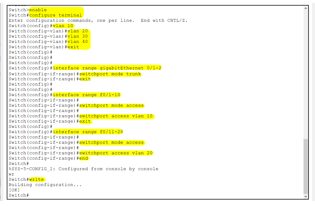
Switch>enable
Switch#configure terminal
Enter
Global Configuration Modemode
Switch(config)#vlan 10
Switch(config-vlan)#vlan 20
Switch(config-vlan)#vlan 30
Switch(config-vlan)#vlan 40
Switch(config-vlan)#exit
Create 4 VLANs
Switch(config)#interface range gigabitEthernet 0/1-2
Switch(config-if-range)#switchport mode trunk
Switch(config-if-range)#exit
Define ports g0/1 and g0/2 as Trunk mode (*all VLAN data is transmitted through this interface to the client device)
Switch(config)#interface range fastEthernet 0/1-10
Switch(config-if-range)#switchport mode access
Switch(config-if-range)#switchport access vlan 10
Switch(config-if-range)#exit
Assign ports f0/1-10 to Vlan10
Switch(config)#interface range fastEthernet 0/11-20
Switch(config-if-range)#switchport mode access
Switch(config-if-range)#switchport access vlan 20
Switch(config-if-range)#end
Assign ports f0/11-20 to Vlan20
Switch#write
Save
Switch2
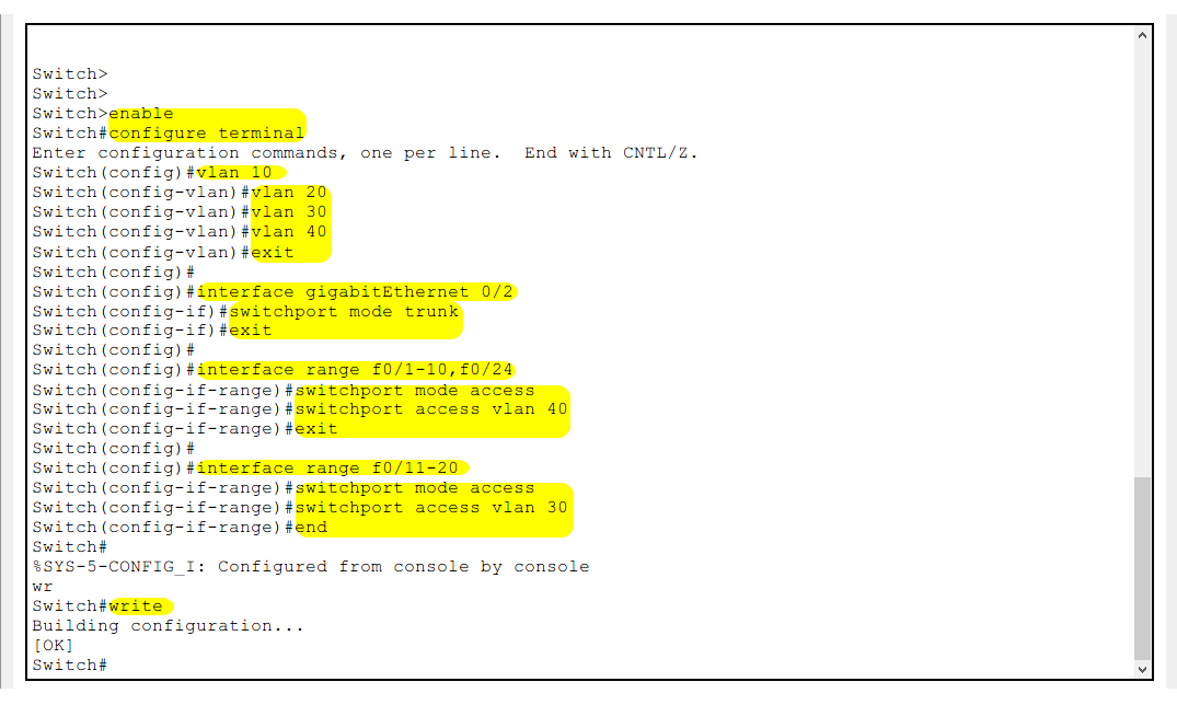
Switch>enable
Switch#configure terminal
Enter
Global Configuration Modemode
Switch(config)#vlan 10
Switch(config-vlan)#vlan 20
Switch(config-vlan)#vlan 30
Switch(config-vlan)#vlan 40
Switch(config-vlan)#exit
Create 4 VLANs
Switch(config)#interface range gigabitEthernet 0/2
Switch(config-if)#switchport mode trunk
Switch(config-if)#exit
Define port g0/2 as Trunk mode (* connect to port g0/2 of Switch1)
Switch(config)#interface range fastEthernet 0/1-10,f0/24
Switch(config-if-range)#switchport mode access
Switch(config-if-range)#switchport access vlan 40
Switch(config-if-range)#exit
Assign ports f0/1-10 and f0/24 to Vlan40
Switch(config)#interface range fastEthernet 0/11-20
Switch(config-if-range)#switchport mode access
Switch(config-if-range)#switchport access vlan 30
Switch(config-if-range)#end
Assign ports f0/11-20 to Vlan30
Switch#write
Save
Test DHCP IP Assignment
Now, we can test the DHCP IP assignment by setting the PCs in each VLAN to obtain IP addresses automatically.
If the configuration is correct, they should receive IP addresses within their respective VLANs’ IP ranges from the DHCP Server.

The IP address assigned to PC1 is 192.168.10.11 (vlan10 network segment)
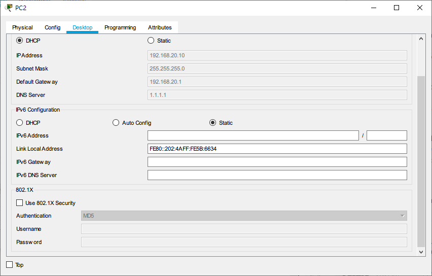
The IP address assigned to PC2 is 192.168.20.10 (vlan20 network segment)

The IP address assigned to PC3 is 192.168.30.10 (vlan30 network segment)
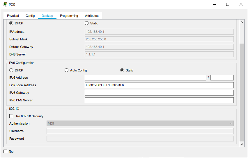
The IP address assigned to PC0 is 192.168.40.11 (vlan40 network segment)
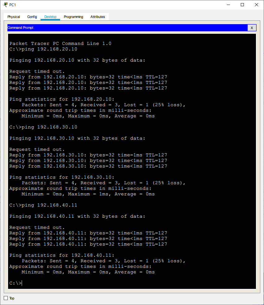
PC1 Ping PC2, PC3, PC0 (can communicate with each other)
Conclusion:
In this example configuration, the PCs in vlan10, vlan20, vlan30, and vlan40 have successfully obtained IP addresses from the DHCP Server in vlan40. The IP Helper (DHCP Relay Agent) has successfully helped in relaying the DHCP requests and responses between the clients and the DHCP server across different VLANs.