Introduction:
Inter-VLAN Routingmeans enabling communication between originally isolatedvlans, andRouter on a Stick(also called single-arm routing) refers to implementingvlancommunication on a single port of a router.
Objective:
Configure multiple
vlangroups on a single router port and enable communication between differentvlans.
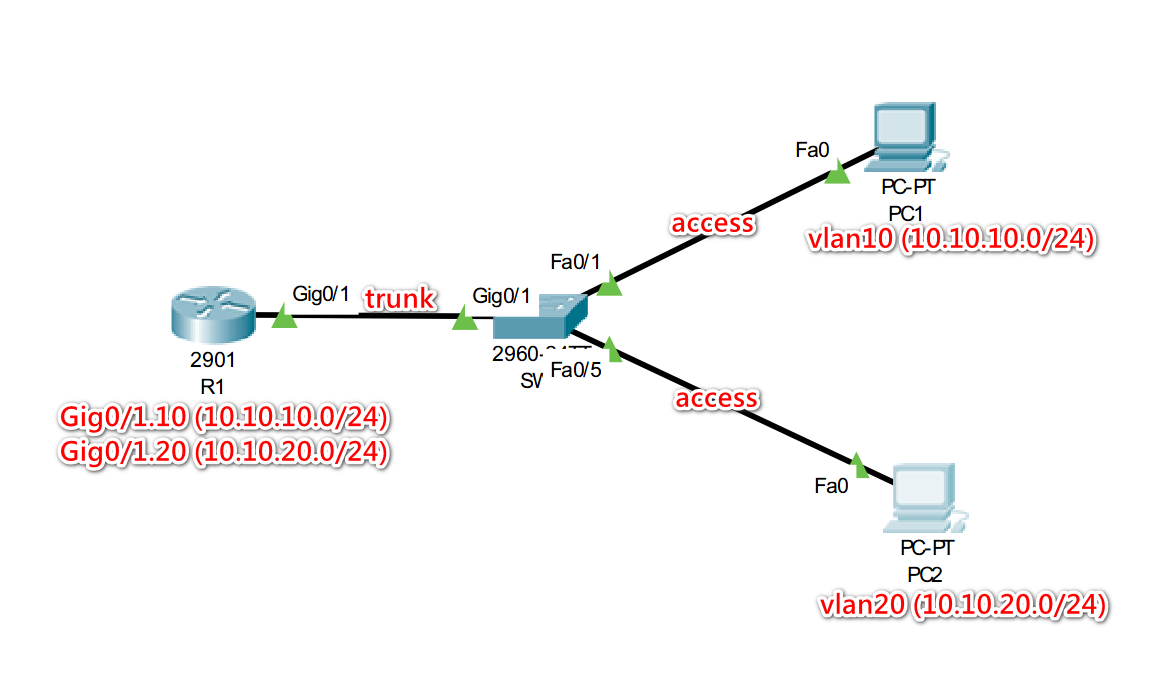
Simulation Scenario:
| vLan | IP(Subnet) |
|---|---|
| vlan10 | 10.10.10.0/24 |
| vlan20 | 10.10.20.0/24 |
PC1 is in vlan10, PC2 is in vlan20, the IPs of the two computers are in different segments, and the router settings allow PC1 and PC2 to communicate with each other.
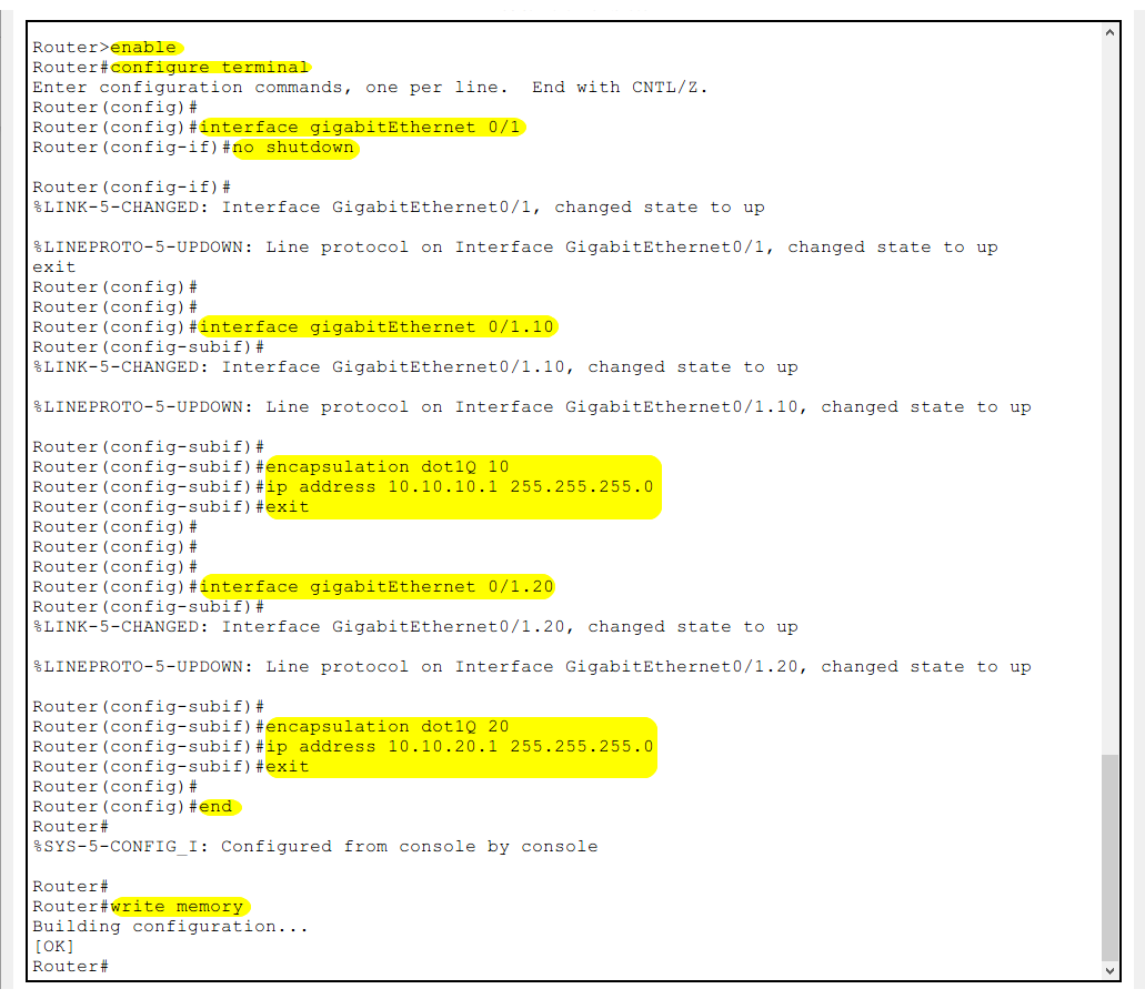
Router Settings (Cisco 2901)
Router>enable
Router#configure terminal
Enter
Global Configuration Mode
Router(config)#interface gigabitEthernet 0/1
Router(config-if)#no shutdown
Router(config-if)#exit
Select physical port 0/1 and enable it
Router(config)#interface gigabitEthernet 0/1.10
Router(config-subif)#encapsulation dot1Q 10
Router(config-subif)#ip address 10.10.10.1 255.255.255.0
Router(config-subif)#exit
Configure sub-interface on physical port 0/1
Configure 802.1Q protocol and assign vlan10
Set the IP address of the interface
Router(config)#interface gigabitEthernet 0/1.20
Router(config-subif)#encapsulation dot1Q 20
Router(config-subif)#ip address 10.10.20.1 255.255.255.0
Router(config-subif)#end
Configure sub-interface on physical port 0/1
Configure 802.1Q protocol and assign vlan20
Set the IP address of the interface
Router#write memory
Save the configuration
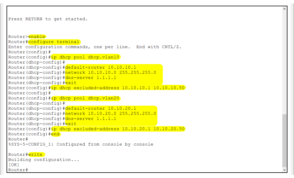
DHCP Server Setup on the Router
Router>enable
Router#configure terminal
Enter
Global Configuration Mode
Router(config)#ip dhcp excluded-address 10.10.10.1 10.10.10.50
Router(config)#ip dhcp pool dhcp.vlan10
Router(dhcp-config)#default-router 10.10.10.1
Router(dhcp-config)#network 10.10.10.0 255.255.255.0
Router(dhcp-config)#dns-server 1.1.1.1
Router(dhcp-config)#exit
10.10.10.1 - 10.10.10.50 are reserved IP address segments, not assigned to devices.
Create an address allocation pool named dhcp.vlan10
Default router IP address 10.10.10.1
Network segment is 10.10.10.0/24
DNS server is 1.1.1.1
Router(config)#ip dhcp excluded-address 10.10.20.1 10.10.20.50
Router(config)#ip dhcp pool dhcp.vlan20
Router(dhcp-config)#default-router 10.10.20.1
Router(dhcp-config)#network 10.10.20.0 255.255.255.0
Router(dhcp-config)#dns-server 1.1.1.1
Router(dhcp-config)#exit
10.10.20.1 - 10.10.20.50 are reserved IP address segments, not assigned to devices.
Create an address allocation pool named dhcp.vlan20
Default router IP address 10.10.20.1
Network segment is 10.10.20.0/24
DNS server is 1.1.1.1
Router(config)#end
Router#write memory
Save the configuration
Switch Settings (Cisco 2960)
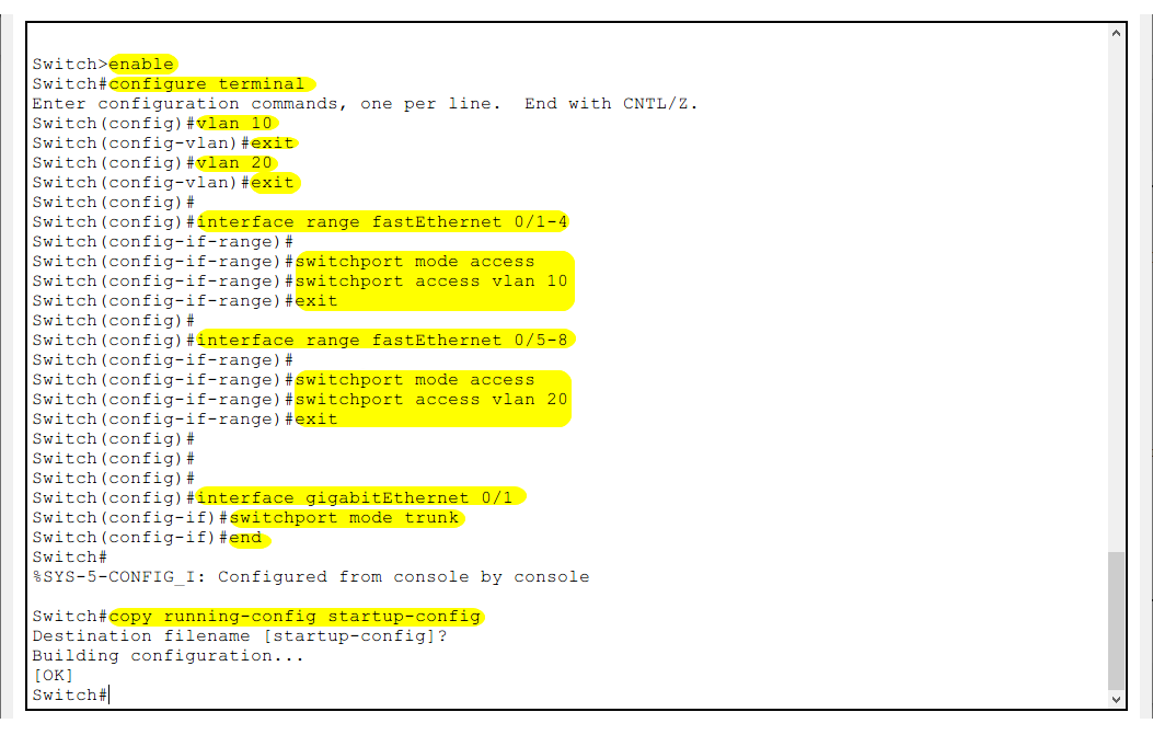
Switch>enable
Switch#configure terminal
Enter
Global Configuration Mode
Switch(config)#vlan 10
Switch(config-vlan)#name vlan10
Switch(config-vlan)#exit
Create and name vlan10
Switch(config)#vlan 20
Switch(config-vlan)#name vlan20
Switch(config-vlan)#exit
Create and name vlan20
Switch(config)#interface fastEthernet 0/1
Switch(config-if)#switchport mode access
Switch(config-if)#switchport access vlan 10
Switch(config-if)#exit
Configure port 0/1 in access mode and assign it to vlan10
Switch(config)#interface fastEthernet 0/2
Switch(config-if)#switchport mode access
Switch(config-if)#switchport access vlan 20
Switch(config-if)#exit
Configure port 0/2 in access mode and assign it to vlan20
Switch(config)#interface fastEthernet 0/24
Switch(config-if)#switchport mode trunk
Switch(config-if)#exit
Configure port 0/24 in trunk mode to connect to the router
Switch(config)#end
Switch#write memory
Save the configuration
Test Connectivity
Connect PC1 to
FastEthernet 0/1and PC2 toFastEthernet 0/5on the switch. Connect the router’sGigabitEthernet 0/1port to the switch’sGigabitEthernet 0/1port. Set PC1 and PC2 to obtain IP addresses automatically. They should receive IP addresses from their respective DHCP pools.
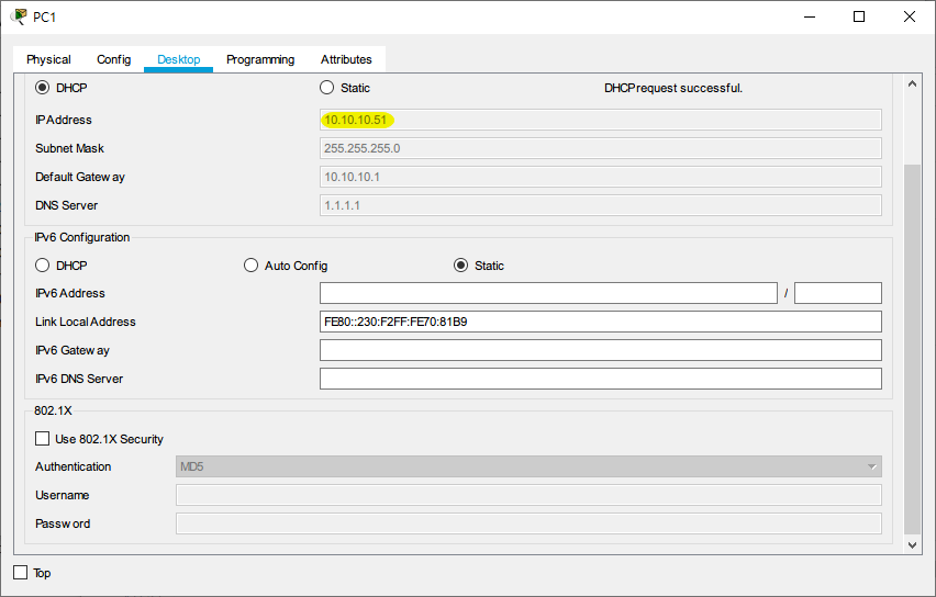
PC1 is assigned the IP address 10.10.10.51 (vlan10 network segment)

PC2 is assigned the IP address 10.10.20.51 (vlan20 network segment)
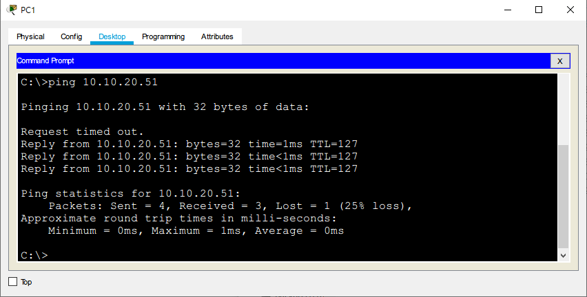
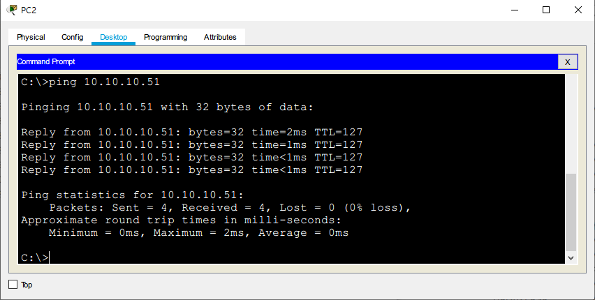
Test connectivity between PC1 and PC2 by using the ping command.
Conclusion:
We be able to successfully send and receive packets between PC1 and PC2, even though they are on different VLANs. This demonstrates successful inter-VLAN communication using the Router on a Stick method.